I ran into a couple minor issues upgrading to the new VMware vCenter Server Appliance 6.7 and wanted to document them in case it happens again to me or someone else that may come across this.
First, make sure your VCSA root password has not expired and set the root shell to be bash. This solved the error of it giving an error that the credentials were not valid despite the installation logs showing that it was in fact logging in but getting an error trying to run ‘date’.
Second, set DRS to ‘Partially Automated’ on your cluster you are deploying this to during the installation so that your new appliance does not move in the middle. This will cause the upgrade to freeze without any errors on the installer side.
The TP-Link HS110 works really well as a smart outlet. They often are on sale along with the wall switches and I’ve found them to be more reliable than the Wemo equivalents. Home Assistant also supports these easily with the tplink component. The nice thing about the HS110 is that it also reports the power usage going through the plug. I use this specifically to monitor the power usage of my home network racks.
The only bad thing is that it doesn’t expose it directly as a sensor. This isn’t an issue for automations, etc as you can use the templating to extract the value but it is annoying when you just want a simple display of the power usage. To get around this, the template switch component allows parts of another item in home assistant to be extracted and turned into a sensor of its own.
Here is an example using the HS110 to show the current power usage of server racks:
sensor:
  - platform: template
    sensors:
      server_rack_power:
        entity_id: switch.server_racks
        value_template: "{{ states.switch['server_racks']['attributes']['Current consumption'] | replace( ' W', '') }}"
        friendly_name: "Server Rack Power Usage"
        unit_of_measurement: "W"
Note that I strip off the wattage symbol fromt he value as it is hard coded into the output.
Update: Home Assistant changed the configuration to require that the entity id be specified. The example has been updated above.
I use a Philips Hue motion sensor on my front deck to turn on some Hue lights in the front deck and driveway after the sun goes down. It’s cheap and despite it not being rated for outdoors it has had no issues surviving a winter outside under the edge of my front decks roof.
I wanted to be able to directly integrate this into Home Assistant, but while it supports the lights I couldn’t find a way to have it integrate the motion sensors. It turns out the API can be easily accessed at the URL http://yourhuebridgeaddress/api/yourusername/sensors/. You will need to follow the instructions from Philips to setup your own userid but it’s pretty simple. This will then expose a simple JSON output that Home Assistant can easily parse with its RESTful sensor component. Polling is not ideal for motion detection, but it hasn’t been an issue so far.
The first thing I noticed was that there were a lot more sensors showing up than just the motion portion I expected. It seems that this sensor has a daylight sensor and temperature sensor built in that aren’t really exposed well even in the Hue app.
One thing to note as well is that the temperature sensor presents the data as an integer despite it including two decimals of precision so you need to make sure to account for that in your sensor by dividing by 100. Example would be:
- platform: rest
  resource: "http://yourhuebridgeaddress/api/yourusername/sensors/sensornumber"
  name: "Hue Motion Sensor Temperature"
  value_template: '{{ value_json.state.temperature / 100 }}'
  scan_interval: 1
  unit_of_measurement: "°C"
You can get the light level like so:
- platform: rest
  resource: "http://yourhuebridgeaddress/api/yourusername/sensors/sensornumber"
  name: "Hue Motion Sensor Light Level"
  value_template: '{{ value_json.state.presence }}'
  scan_interval: 1
And of course the motion detection that this device is supposed to be used for:
- platform: rest
  resource: "http://yourhuebridgeaddress/api/yourusername/sensors/sensornumber"
  name: "Hue Motion Sensor Motion"
  value_template: '{{ value_json.state.status }}'
scan_interval: 1I have two LG heat pumps that I use for heating and cooling in the house. These are mini-splits that operate only with a remote and do not have a centralized thermostat that I can easily replace. It doesn’t help that the device itself is pretty bad at working at maintaining a temperature instead of just always blasting out air at a single temperature. I originally tried the Z-wave ZXT-120 IR Extender with SmartThings but had many issues getting it to reliably control the unit. I wanted something anyway that I could extend to other devices near by that also used IR if needed anyway.
The solution so far has been the Broadlink RM pro which does both IR and RF remote control emulation. Home Assistant has a Broadlink component that allows you to directly control IR/RF actions as a switch.
The biggest complaint/issue is how you need to get the IR/RF codes. The easiest way I found was to learn them directly from the remote using the Broadlink app in Android and then following the instructions on the Broadlink component page under ‘Using E-Control Remotes’ sections.
Here is my configuration for Home Assistant with a switch for cooling and heating at predetermined settings.
switch:
  - platform: broadlink
    host: 123.123.123.123
    mac: '00:00:00:00:00:00'
    switches:
      heatpump_cool:
        friendly_name: "Heatpump Cooling"
        command_on: 'JgBAAAABJIkRNBIPEhIPFA42DhQOFQ8SEBMQExATDhQOFA8UDhQPFA4TDzYPFA42DxIQNg4TEBMPNQ8UDxMJPA0ADQUAAAAAAAAAAA=='
        command_off: 'JgBAAAABJIkQNRESDxMQEBMzEREQEw8TDzURMxEREREQExASEBIQEw8TEBMQEhASEBMQNBERETQQEhEREBMQNBEADQUAAAAAAAAAAA=='
      heatpump_heat:
        friendly_name: "Heatpump Heating"
        command_on: 'JgBAAAABI4oQNQ8TEBIQEg81EBMPEw8TEBMPEw8UEBIPFA81EBMPExASDzUQEhASEBIREg81EBIQNRASEDQQEw8ADQUAAAAAAAAAAA=='
        command_off: 'JgBAAAABJIkQNRESDxMQEBMzEREQEw8TDzURMxEREREQExASEBIQEw8TEBMQEhASEBMQNBERETQQEhEREBMQNBEADQUAAAAAAAAAAA=='
As you can see this is somewhat limiting as there is really only binary choices on heating and cooling and not at particular temperatures. The LG heat pumps I have have remotes that have displays so they have to send the entire configuration state in a large chunk of IR data each time and the individual controls are not easily exposed. I can go back and choose a few different options if need be but for now this works pretty well as I really just need the heat pumps to spit out hot or cold air like any other furnace.
To wrap this up in a way that makes automation simple I setup a generic thermostat in Home Assistant like so:
climate:
  - platform: generic_thermostat
    name: 'Main Floor'
    heater: switch.heatpump_cooling
    target_sensor: sensor.living_room_temperature
    ac_mode: true
    target_temp: 22
    tolerance: 1.0
    min_cycle_duration:
      seconds: 120
Right now the ‘ac_mode’ is hard coded in the configuration but I need to look into ways to automate switching this at different times. There is also no way to really turn off a generic thermostat right now in Home Assistant so an automation is used to set the target temperature very high (or low if ac_mode is off in the winter) to stop any actions.
automation:
  - alias: "Disable Thermostats at Night"
    trigger:
      platform: time
      at: "20:00:00"
    action:
      service: climate.set_temperature
      data:
        entity_id: climate.main_floor
        temperature: 32

  - alias: "Enable Thermostats in Morning"
    trigger:
      platform: time
      at: "07:30:00"
    action:
      service: climate.set_temperature
      data:
        entity_id: climate.main_floor
        temperature: 22
Obviously this is not perfect and a more precise IR control method would be preferred but this get the job done and has drastically reduced the power usage from the heat pumps in the summer.
The washer and dryer that we have doesn’t have any sort of remote notification of load status other than a loud beep. Since it is in the basement in a closed room we often forget or just don’t know when the loads are complete. I wanted a way to see in near real time what the status of the load was in at least an “on/off” fashion remotely as well as receive notifications when loads were complete.
I tried doing this first with an ESP8266 and some vibration sensors. While it somewhat worked, it was difficult to get an accurate reading even with a pretty sensitive gyroscope replacing the vibration sensor. It was especially difficult on the washer as it often would stop moving during its cycle as it filled, soaked and drained. After quite a bit of fiddling I abandoned this method.
I was already using a Z-Wave Aeotec Home Energy Meter to measure my entire house power usage so I knew it was fairly accurate even though it used CT clamps. I bought two more of these devices in the older versions as they were very cheap on eBay. While I use HomeAssistant as my main home automation hub, I still use SmartThings as a bridge for the Z-Wave and Zigbee devices via MQTT.
The default device handler in SmartThings doesn’t have a very quick update frequency so I used a custom device handler that had a much quicker and adjustable frequency. Note that this is only for the Gen1 devices.
After installing a single clamp on one to the feed wires for the washer and a single clamp on the other to the same for the dryer I could then see the current wattage draw of the appliances. Usual warnings apply here for working inside your electrical panel. Don’t do the install yourself if you aren’t comfortable and know what you are doing. I probably could have done this for the washer with one of the outlets that measure current but that wouldn’t work for the dryer and its 240V outlet. Being consistent with the measuring device made sense in the end.
Once I had these in Home Assistant I could easily build automations around it to send me notifications. I decided to use some input booleans for the state so I could flip them on and off through the automations as well as easily test the notification portion without having to start and stop the actual appliances. I also needed to make sure that the washer notification only triggered after so many minutes of low wattage usage since the accuracy of the meters wasn’t quite good enough to always deal with the washer in its ‘quiet’ parts of the cycles using very little power. Home Assistant handled this easily with the ‘for’ time condition on the state change.
It ends up looking like this in Home Assistant for me:
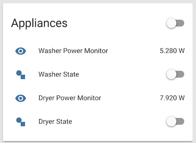
Example automations are below, make sure to tweak the wattage values and time threshold for the washer to what makes sense.
automation:
- alias: "Washer On Threshold"
  trigger:
    platform: numeric_state
    entity_id: sensor.washer_power_monitor
    above: 50
  action:
    service: homeassistant.turn_on
    entity_id: input_boolean.washer_state

- alias: "Dryer On Threshold"
  trigger:
    platform: numeric_state
    entity_id: sensor.dryer_power_monitor
    above: 100
  action:
    service: homeassistant.turn_on
    entity_id: input_boolean.dryer_state

- alias: "Washer Off Threshold"
  trigger:
    platform: numeric_state
    entity_id: sensor.washer_power_monitor
    below: 51
  action:
    service: homeassistant.turn_off
    entity_id: input_boolean.washer_state

- alias: "Dryer Off Threshold"
  trigger:
    platform: numeric_state
    entity_id: sensor.dryer_power_monitor
    below: 101
  action:
    service: homeassistant.turn_off
    entity_id: input_boolean.dryer_state

- alias: "Washer Finished Notification"
  trigger:
    platform: state
    entity_id: input_boolean.washer_state
    from: 'on'
    to: 'off'
    for:
      minutes: 8
  action:
    - service: notify.ios_iphone
      data:
        message: "Washer has finished it's load"

- alias: "Dryer Finished Notification"
  trigger:
    platform: state
    entity_id: input_boolean.dryer_state
    from: 'on'
    to: 'off'
  action:
    - service: notify.ios_iphone
      data:
        message: "Dryer has finished it's load"
    - service: notify.ios_kim_anthony_iphone
      data:
message: "Dryer has finished it's load"The H801 is a cheap LED Wifi controller for analog LED strips. It’s built in firmware is fairly useless using anything but their Android app but the best part is it uses an ESP8266 inside so it can be reflashed into something much more useful. I specifically converted mine to a firmware that speaks MQTT so that I can integrate easily into Home Assistant.
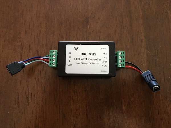
Opening the H801 is very easy, only 4 screws on the bottom. The board is hot glued to the bottom so it may take a bit of effort to pop it off. Watch the wires on the bottom when pulling the PCB out.
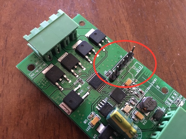
There are 6 pins that will need headers added to them. One in a group of 4 and another in a group of 2. Simply solder headers to these and then you can proceed.
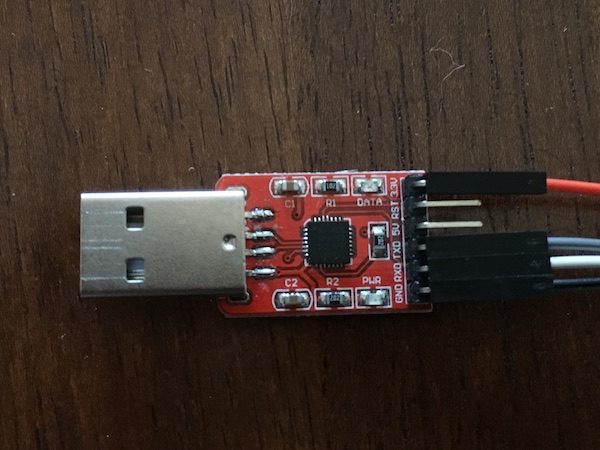
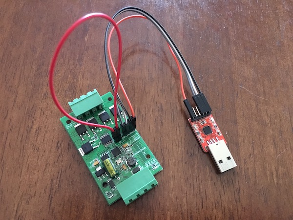
You will need a USB to UART/TTL/Serial adapter to reflash these as there is not one on board. I use a CP2102 based one here bought off of Aliexpress.
Simply hook the 3.3v, ground, transmit and receive wires up between the headers you just soldered on and the USB to UART/TTL/Serial adapter. You will need to use a jumper wire to connect the remaining two pins together on J3 to put the board into flash mode. Make sure you use the 3.3v for power NOT the 5v as the ESP8266 is not 5v tolerant here.
Download and install the Arduino IDE. Once installed Ensure that http://arduino.esp8266.com/stable/package_esp8266com_index.json is listed in the additional board manager URL field within the preferences. In the Boards Manager you will then be able to find the ESP8266 and install. You will also need to make sure that the following libraries are installed in the Library Manager:
- WifiManager
- PubSubClient
- ArduinoOTA
There is not a predefined board configuration for the H801 setup so you will need to set your board information as follows:
- Board: Generic ESP8266
- Flash Size: 1M (64K SPIFFS)
- Upload Speed: 115200
Make sure you have disconnected any other external power and LED strips from the H801 and then plug in the USB adapter. The USB adapter will power the H801 while we flash. You should see a new port show up in the Arduino software which can be chosen.
Open the mqtt.ino software previously mentioned above and edit the MQTT server details as needed. Next, flash the firmware to the ESP8266 which should take about 20 seconds or so.
Unplug the wiring and power the H801 via its VCC/ground pins instead of USB. You should see a new Wifi network appear for the ESP which you can connect to on a phone / laptop. Go to http://192.168.4.1 in a browser and setup your Wifi.
Once you are done this you should see the green LED on the H801 flash multiple times after it is rebooted which means it has successfully connected to the Wifi and MQTT server.
I found it easiest to connect this to power by connecting a cheap barrel jack with screw terminals via short lengths of wire to the terminals on the H801. I also sacrificed an LED extension cable with the common 4-pin plug for the LED connection terminals to make it easier to connect and disconnect.
With the release of vSphere 6.0 U2 and VSAN 6.2 I was eager to upgrade to get the new features of VSAN. I run a 3 node cluster at home with an SSD and magnetic disk in each node. Unfortunately the straight upgrade isn’t as easy as expected due to this, admittedly, bad setup if this wasn’t just a home lab. You will get a similar error:
A general system error occurred: Failed to evacuate data for disk uuid 522de09d-50f0-083a-0cc6-ee47c89787b2 with error: Out of resources to complete the operation
The way around this is to force the upgrade allowing you to enter a much less redundant scenario. I would obviously NOT do this on anything you consider hugely important and instead reevaluate your VSAN configuration to ensure redundancy in this situation. If you do want to go ahead, make sure your backups are current, log into the shell of your VCSA and run the following command replacing the $ variables with your names:
vcenter:~ # rvc administrator@vsphere.local@localhost> vsan.v2_ondisk_upgrade /$vcserver/$dc/computers/$clusterThings should kick off at this point and go through the whole process. You WILL get warnings about VSAN health in the client during this as you are going to be running reduced redundancy and requiring resyncs. Expect this to take a very long time.
Again, do not do this in a situation where data loss matters.
I’ve been integrating multiple parts of my home lately with SmartThings and wanted to get my garage door opener attached as well. There are multiple off the shelf products for this but they all are fairly expensive for what they do and some work better than others. I wanted to keep my existing opener and switches while adding the ability to control it automatically and remotely. Being able to see when the door is left open by accident is a plus as well.
Moving the door is as simple as just connecting the two terminals together just like the wall switch does. Since this is a higher voltage than a micro controller can handle on its own using a relay was necessary. I chose the Particle Photon as the microcontroller as it let me use Arduino libraries but gave me a quick way to get an API end point on the internet without any fuss. These are great and at $19 USD they are well worth the ease of use over something like an cheaper ESP8266.
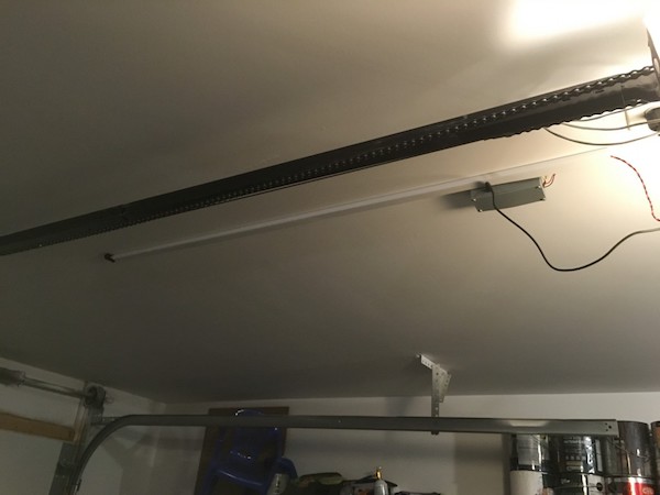
I also wanted to be able to reliably detect the state of the door which required some sort of sensor. I already had a spare IR distance sensor on hand from a different project so I mounted this to the ceiling pointing down above where the door was while open. This meant that when the door was closed the IR distance sensor would not detect it but when opened it would reflect the beam and indicate the door was present. It was unlikely anything else would get in the way to present a false reading as well given the range of the sensor. The sensor is analog so was very easy to read on the Photon. I just had to establish rough range values by reading it and holding my hand at various distances to figure out a good threshold to consider that it was the door in the way of the sensor and not someone standing below it or a car in the garage.
Once I had the physical control working via the Particle API the integration with SmartThings was next. This required writing a device type for the Particle Photon that defined the API calls in the Particle Cloud service as well as allowing me to easy put my API credentials in. Since I wanted the distance sensor to be able to report back the state of the door without being polled I also had to write a SmartApp which allowed the Photon to update SmartThings via an API endpoint in the SmartApp.
In the end this worked quite well and ended up costing about $30 USD so pretty reasonable.
All the files with the Photon and SmartThings code as well as the 3d printable case model can be found in my Github repository.
I wanted a way to monitor our home’s water consumption as we’ve had a few running toilets that hadn’t been caught for too long. Since the meter is buried under the stairs in a storage area it’s annoying to get to to read regularly so I wanted an automated somewhat realtime method.
My meter is a Neptune T-10 meter that has a few ways to read. There is a large dial as well as a small higher resolution spinning triangle. These meters also have a magnet inside that rotates with the flow that is monitored by the water company.
The magnet seemed the most obvious method but unfortunately every hall effect sensor I tried could not read the magnet through the casing. The only place that appears you can easily do this is where the remote monitoring that the water utility uses is located. I couldn’t really mess with this, and after a brief thought of intercepting the water companies signals, I temporarily gave up on the magnet path.
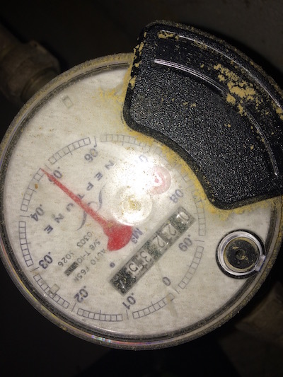
My next attempt was using a SY310 photo sensor. This sensor can detect dark to light color changes and I had opened to catch the tips of the red triangle as it rotated. Other people had success with this method on similar meters, but my meter cover was too scratched and reflected/scattered way too much IR for this to work properly. You can see in the photo above how textured the top is and how the flash scattere, this didn’t help. After an hour of trying to get it to read while stuffed under my stairs with a laptop I went back to the drawing board.
I started looking at different ways to detect the magnet again that were much more sensitive. I found a few magnetometers in compass break out boards that seemed to have very high sensitivity and seemed to fit the bill perfectly. I ordered a HMC5883L breakout from adafruit and after hooking it up to a spare Raspberry Pi I was able to notice a change in the readings when water was running. I had the most consistency when facing the breakout against the monitor so that the Y axis would catch the magnet approaching and then leaving. This meant that I was getting a nice positive to negative oscillation that I could count.
I found some code for an arduino that solved the same problem and ported this to Python to be used on my RPi. I also added uploads to both GroveStreams and ThingSpeak to make sure it was tracked and graphed (still deciding on the end provider so using both).
The end result so far looks like this:
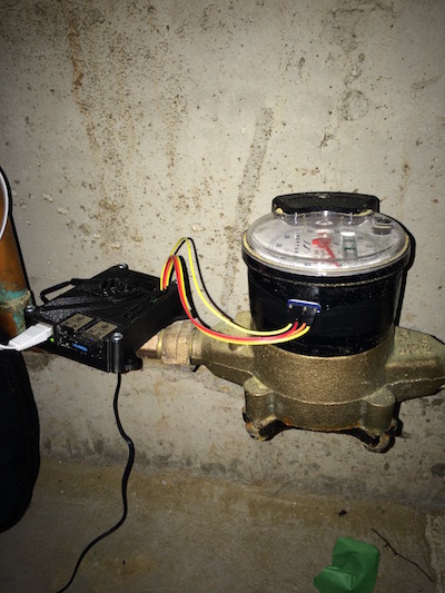
Obviously some longer wires and properly mounting the RPi is in order but it works well for now. Here is a live view from thingspeak.
You can find the code and wiring instructions for the HMC5883L in my github watermon repo.
Going forward I will probably replace the RPi with something like a Particle Photon or other Wifi microcontroller but for now the RPi works well. It was much easier to debug via SSH as well while writing the code than constantly programming under the stairs.
I use a Wemo Insight Switch to turn a lamp on and off for my prints and had been doing it manually via the Wemo app. Instead, it made a lot more sense to have this just happen automatically via OctoPrint so that I could always see what was printing and then not waste energy after the print was done. Turns out OctoPrint has a great events handler that lets you do just this as long as you can perform the action you want via shell script or gcode.
I use OctoPrint on a Raspberry Pi using OctoPi so I had to perform the following commands to install
sudo apt-get install python-setuptools python-dev
easy_install ouimeaux
If you have issues, check the Ouimeaux installation docs.
This will give you /usr/local/bin/wemo which can be used to control your lights. To see available devices:
/usr/local/bin/wemo listVerify that you can control your switches like so:
/usr/local/bin/wemo switch "3d Printer Light" on
/usr/local/bin/wemo switch "3d Printer Light" off
You will then need to add the following to the ~/.octoprint/config.yaml file:
events:
  enabled: true
  subscriptions:
  - command: /usr/local/bin/wemo switch "3d Printer Light" on
    event: PrintStarted
    type: system
  - command: /usr/local/bin/wemo switch "3d Printer Light" off
    event: PrintDone
    type: system
  - command: /usr/local/bin/wemo switch "3d Printer Light" off
    event: PrintFailed
    type: system
  - command: /usr/local/bin/wemo switch "3d Printer Light" off
    event: PrintCancelled
    type: system
Substitute the name of your switch / light in the config above where I used ‘3d Printer Light’. Restart OctoPrint and you are good to go. While I am using a switch here and a small LED lamp, you can do this with a Wemo bulb as well without any issues.